EN
EN

A box build assembly is the integration of printed circuit board assemblies, cables, mechanical parts, displays, power supplies and other components into an enclosure or finished electronic product. It is also known as systems integration, electromechanical assembly or final product assembly.
The scope can range from installing one PCBA into a small plastic housing to building a complex cabinet containing multiple circuit boards, cable harnesses, controls, displays and power modules. Programming, functional testing, labeling and final packaging may also be included.
Because “box build” does not describe one standardized production package, OEM buyers must define exactly where the supplier’s responsibility begins and ends. A clear scope of work prevents missing components, undocumented assembly steps and unexpected quotation changes.
Reviewed by: GreensTone Engineering Team
Last updated: September 2026
Box build assembly includes the electronic, mechanical and software-related operations required to convert separate parts into a complete unit or functional subsystem.
The exact content depends on the product. A simple project may require only a PCBA, cable and enclosure. A more complex system can involve hundreds of electronic and mechanical parts, multiple firmware versions, dedicated test fixtures and market-specific packaging.
| Assembly Element | Typical Components or Activities | Information Required from the OEM |
|---|---|---|
| PCB Assembly | SMT, through-hole components, programming, conformal coating and board-level testing | Gerber files, BOM, pick-and-place data, schematics and assembly drawings |
| Cables and Wire Harnesses | Cutting, stripping, crimping, connector installation, labeling and continuity testing | Wire list, cable drawings, connector specifications and pin assignments |
| Mechanical Parts | Sheet-metal chassis, machined parts, brackets, fasteners and heat sinks | 2D drawings, 3D files, materials, tolerances and surface-finishing requirements |
| Plastic Components | Injection-molded enclosures, covers, supports, buttons and cosmetic parts | CAD files, resin requirements, color references, finishes and approved samples |
| Final Integration | PCBA installation, cable routing, display mounting, fastening and enclosure closure | Assembly instructions, drawings, torque requirements and approved product sample |
| Programming and Configuration | Firmware loading, serial-number assignment and product configuration | Approved firmware, programming procedure and configuration rules |
| Testing and Inspection | Electrical checks, functional testing, visual inspection and final quality audit | Test procedure, fixtures, limits, expected results and defect criteria |
| Packaging | Labels, accessories, manuals, protective packaging and shipping preparation | Artwork, labeling rules, packing instructions and destination requirements |
The scope should also identify which materials are supplied by the customer and which are purchased by the box build manufacturer. Every component should be connected to an approved BOM, drawing or controlled specification.
PCBA produces an assembled circuit board, while box build assembly integrates that PCBA with cables, mechanical parts, software and an enclosure to create a higher-level assembly or complete product.
| Comparison Area | PCB Assembly | Electromechanical Subassembly | Box Build Assembly |
|---|---|---|---|
| Delivered Output | A populated and tested circuit board | A module containing electronic and mechanical parts | A complete unit, cabinet or market-ready product |
| Typical Components | Bare PCB, SMDs, through-hole parts and connectors | PCBA, cables, brackets, sensors or power modules | Multiple PCBAs, wiring, displays, controls, enclosure and accessories |
| Manufacturing Processes | SMT, through-hole soldering, inspection and board testing | Mechanical fastening, wiring and module testing | Full system integration, configuration, functional testing and packaging |
| Main Documentation | Gerber, BOM, pick-and-place file and assembly drawing | Module BOM, mechanical drawings and wiring instructions | Complete product BOM, CAD files, assembly instructions, firmware and test plan |
| Typical Test Level | Board-level electrical or functional testing | Module-level functional verification | Complete product function, configuration and final inspection |
An OEM may purchase PCB assembly services from one supplier and complete the remaining integration internally. A box build model transfers more manufacturing responsibility to the contract manufacturer.
The correct boundary depends on the OEM’s internal resources, product complexity, intellectual property strategy and test requirements. It should be documented in the RFQ rather than inferred from the term “box build.”
The box build assembly process converts controlled product files and approved materials into a configured, tested and packaged electronic unit. A typical project follows seven stages.
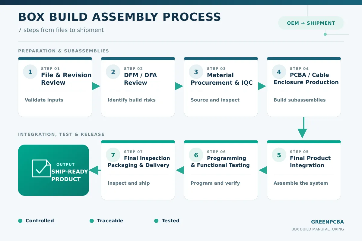
The manufacturer reviews the complete product package before quotation or production. This includes the BOM, PCB data, wiring documents, mechanical drawings, firmware, labels, test procedures and packaging requirements.
All documents should carry a revision number. The BOM, drawings, firmware and test program must refer to the same product configuration. Mixing revisions can produce a unit that passes an outdated test while failing the current design requirements.
Design for assembly evaluates whether the product can be built consistently and inspected efficiently. Typical review points include:
Enclosure and PCBA tolerance stack-up;
Connector accessibility and mating direction;
Cable length, routing and bend radius;
Fastener access and tightening sequence;
Grounding and shielding connections;
Heat-sink contact and thermal interface materials;
Label placement and barcode visibility;
Access to programming and test interfaces.
Resolving these issues before tooling and production reduces rework and prevents technicians from relying on undocumented adjustments.
The manufacturer purchases or receives the approved PCBAs, cables, enclosures, displays, fasteners and other materials. Incoming inspection verifies part numbers, quantities, dimensions, appearance and required documentation.
Critical materials should be linked to supplier and lot information when traceability is required. Alternative parts must go through a written customer-approval process before being introduced into production.
PCB assemblies may be produced using SMT, through-hole or mixed-technology processes. Mechanical work can include sheet-metal fabrication, CNC machining, plastic injection molding and surface finishing. Cables and wire harnesses may require crimping, soldering, labeling and continuity testing.
Each subassembly should pass its designated inspection before final integration. This prevents a known board, cable or enclosure defect from moving into a more expensive assembly stage.
Technicians install PCBAs, cables, controls, displays, power supplies and mechanical parts according to the approved assembly instructions. Process controls may specify cable routes, connector engagement, adhesive application, fastener type and tightening requirements.
A golden unit or an approved first article can provide a visual reference, although it should supplement controlled drawings and work instructions rather than replace them.
Products can be programmed and configured before or after enclosure assembly, depending on access and risk. The test procedure should define the required inputs, operating sequence, measured outputs, acceptable limits and failure-handling process.
A passing indicator alone may be insufficient for a complex product. Test records should identify the unit, firmware version, test result and date when product-level traceability is required.
Final inspection confirms workmanship, product configuration, labels, accessories, cosmetic condition and packaging. Serial numbers and shipping records should match the approved order information.
OEMs that require coordinated electronics, cable, metal, plastic and final-product integration can review GreensTone’s China box build assembly capabilities after defining the required manufacturing scope.
Quality control in box build manufacturing combines material verification, revision control, process inspection, functional testing and final product acceptance.
A box build can contain several individually acceptable components that fail when integrated. Effective quality control must therefore evaluate the complete system as well as its individual parts.
Incoming controls can verify PCBAs, cables, mechanical dimensions, enclosure finishes, displays, labels and customer-supplied materials. Inspection depth should reflect component risk and supplier history.
The first assembled unit confirms that the materials, drawings, work instructions, firmware and test setup match the approved revision. Any required adjustment should be documented before the remaining batch proceeds.
In-process checks may include connector engagement, cable routing, polarity, fastener installation, label placement, grounding connections and cosmetic condition. Critical checkpoints should appear in the work instruction rather than depend on operator memory.
Testing should reflect how the finished product is intended to operate. Depending on the design, it may include power-up checks, current measurements, communication tests, input/output verification, display checks, alarm simulation, firmware confirmation or burn-in testing.
Standards must be selected according to product type and customer requirements. PCB assembly workmanship may be defined with reference to IPC-A-610 and IPC J-STD-001. Cable and wire-harness workmanship may be specified using IPC/WHMA-A-620 when appropriate.
A quality management system such as ISO 9001 provides a framework for controlled processes, documented information, performance evaluation and continual improvement. Buyers should still review the supplier’s actual project controls and current certificate scope.
For products entering the European market, the BOM and material declarations may also need to address the EU RoHS Directive. Compliance responsibility, documentation and applicable exemptions should be defined for the specific product.
CE marking, UL certification and other approvals are product- and market-specific. They should not be treated as general box build quality certificates. The OEM and manufacturing partner must agree on who is responsible for product evaluation, testing files and regulatory documentation.
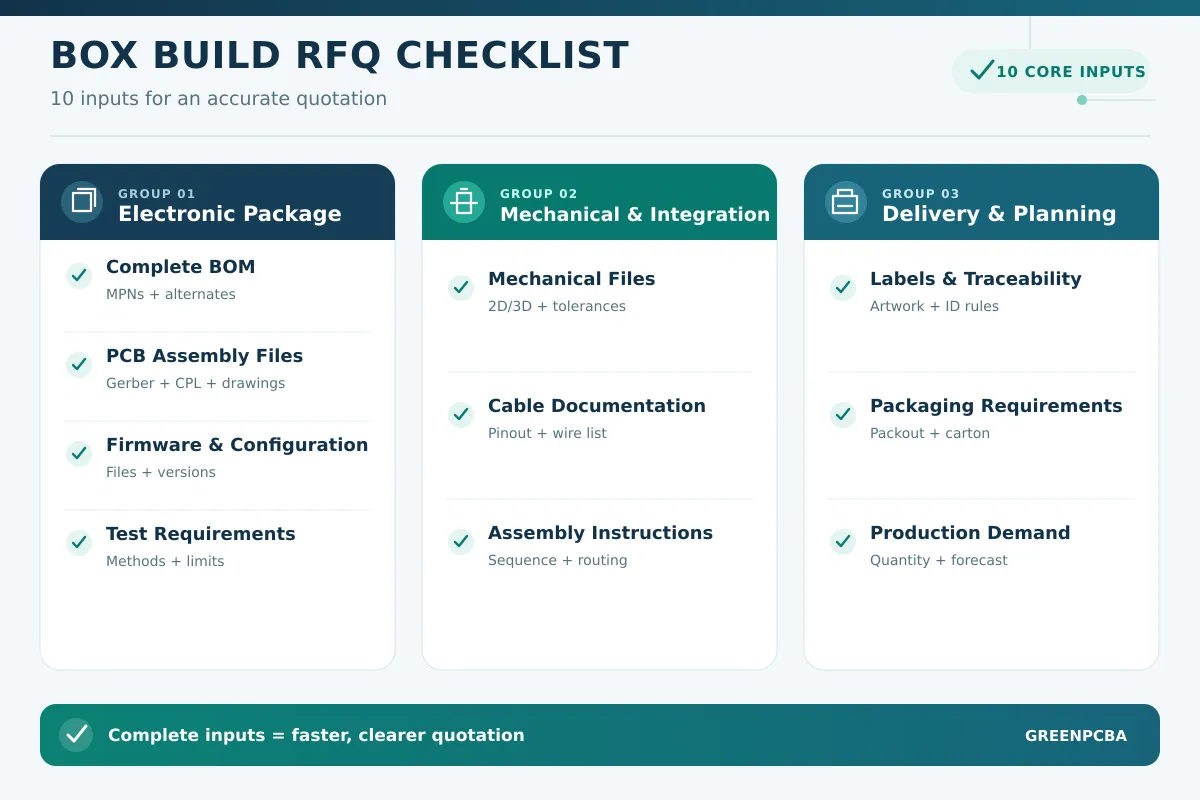
A complete box build RFQ should define the product configuration, approved materials, assembly instructions, testing requirements, production quantities and delivered condition.
| RFQ Item | Information to Provide | Why It Matters |
|---|---|---|
| Complete BOM | Manufacturer part numbers, approved alternatives and customer-supplied items | Defines sourcing responsibility and prevents material assumptions |
| PCB Assembly Files | Gerber, BOM, pick-and-place file, schematic and assembly drawing | Supports PCBA quotation, DFM review and production setup |
| Mechanical Files | 2D drawings, 3D CAD, tolerances, materials and finishes | Allows enclosure, bracket and fit assessment |
| Cable Documentation | Wire list, connector details, pinout, lengths and labeling | Defines cable construction and electrical continuity |
| Assembly Instructions | Assembly order, fastening, cable routing, adhesive and workmanship requirements | Creates a repeatable and auditable process |
| Firmware and Configuration | Approved files, version number, programming method and configuration rules | Prevents incorrect software from entering finished products |
| Test Requirements | Test steps, fixtures, limits, expected results and record-retention needs | Defines how finished-product performance will be accepted |
| Labels and Traceability | Artwork, serial-number format, barcode rules and lot requirements | Connects products to production and test records |
| Packaging | Accessories, manuals, protective packaging and carton requirements | Defines the exact delivered product condition |
| Production Demand | Prototype quantity, batch size, annual forecast and delivery schedule | Supports material, tooling and capacity planning |
The quotation should separate recurring production costs from non-recurring charges such as tooling, test fixtures, programming setup and engineering preparation. This makes supplier quotations easier to compare.
OEM buyers should also ask the following questions:
Which processes are performed internally and which are subcontracted?
How are BOM, drawing and firmware revisions controlled?
How are alternative parts submitted for approval?
Which inspections and tests are included in the quotation?
Can the supplier provide a sample test report?
How are nonconforming products isolated and investigated?
What production data can be traced by serial number or batch?
How will engineering changes be introduced into production?
GreensTone supports OEM box build projects that require PCB assembly, component sourcing, cable assembly, enclosure manufacturing, programming and final product testing through one coordinated production team.
Based in Shenzhen, GreensTone’s published manufacturing scope includes:
Approximately 5,000 m² of workshop space;
Three SMT lines and two DIP or through-hole lines;
SMT components down to 01005;
BGA assembly down to 0.25 mm pitch;
AOI, X-ray, flying-probe, ICT and functional testing options;
Cable and wire-harness assembly;
Plastic injection molding and plastic enclosure production;
CNC machining and sheet-metal fabrication;
Programming, final integration, labeling and packaging.
Previous manufacturing applications include smart meters, EV charging equipment, smart plugs, industrial controls, security equipment and water-treatment or pool-control systems. These products commonly combine PCBAs with cables, displays, power devices and custom enclosures.
GreensTone’s broader electronics manufacturing services can support projects from initial manufacturing review and prototype assembly through low-volume production and recurring orders.
To begin a box build assessment, provide the latest BOM, mechanical and PCB files, wiring information, firmware, test requirements and expected quantities. The engineering and sourcing teams can then identify missing documents, manufacturing risks, material lead times and fixture requirements before final quotation.
A box build assembly brings PCBAs, cables, mechanical components, firmware and testing together as one controlled product-integration process.
The biggest sourcing risk is an unclear scope. A supplier may interpret “box build” as basic PCBA installation, while the OEM expects programming, accessories, product testing, labeling and retail-ready packaging.
A complete RFQ should therefore define every supplied component, assembly step, approval point, test requirement and delivery condition. Once the scope is documented, buyers can compare suppliers using manufacturing capability, engineering support, quality control and total project cost.
A box build assembly may include PCBAs, cables, wire harnesses, displays, controls, power supplies, metal or plastic enclosures, programming, functional testing, labels, accessories and final packaging. The exact scope is defined by the OEM.
PCBA focuses on mounting and soldering electronic components onto a printed circuit board. Box build assembly installs one or more PCBAs into a mechanical system and adds cables, controls, software, testing and packaging as required.
A manufacturer normally needs a complete BOM, PCB production files, mechanical drawings, cable documentation, assembly instructions, firmware, test requirements, labeling files, packaging instructions and expected order quantities.
Yes, provided the manufacturer has suitable internal capabilities or an approved supplier network. The quotation should identify which processes are completed internally, which are subcontracted and how external suppliers are controlled.
Testing can include board-level inspection, cable continuity, firmware verification, power-up testing, input/output checks, communication testing, functional testing and final product inspection. The method should be defined by the product’s actual functions and risks.
Lead time depends on component availability, enclosure tooling, mechanical fabrication, PCBA production, test-fixture development and order quantity. A reliable schedule can only be prepared after the supplier reviews the complete product package and material status.